

Pinned Post
LithiFlex server rack battery communication & connection manual
Batteries connect in parallel
Others
Grouding
Dry connect
SOC calibration
Batteries connect in parallel
1.Daisy Chain Connection
Accessories:
Power cable connect with battery with inverter
T fuse
D25 cable
2.Busbar connection
Accessories:
power cable connect with battery with inverter
S30 or S80
6 slot cabinet | 10 slot cabinet | Bracket rack

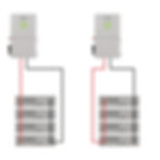
2.1-Single inverter

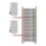
2.2-Multiple inverters
The maximum current for the busbar cross-section is 300A. When multiple inverters are connected, the total current may exceed 300A. In this case, you can change the inverter connection points to ensure that the current in each cross-section of the busbar does not exceed 300A.
Requirements:
The connection points of the battery positive and negative terminals to the busbar should be evenly distributed.
The connection points of the inverters to the busbar should be evenly distributed.
2.3-Multiple inverters & busbars
The wires connecting the busbars should be configured according to the maximum current of the inverter.


Communication Connection
1.Communication Between Batteries
Use standard network cables to connect the communication ports of the batteries. (RS485 cable inclued in the battery package)
Connect the C-down port of the upper-level battery to the C-up port of the lower-level battery. The highest-level battery is the master battery, The othes are slave batteries.
For multiple stacks/cabinets, connect the C-down port of the lowest-level battery in the first stack/cabinet to the C-up port of the highest-level battery in the second stack/cabinet.
All batteries in the second cabinet will be slave batteries.
DIP switch of all slave batteries is default, Pls check image as below.
DIP switch of master battery depends on the inverter brand.

2. Communication between the master battery and the inverter
Connect the C-up port of the master battery to the inverter's BMS interface with communication cable. Different brand inverters have different BMS interfaces, the communication cables

3. Communication connection between the battery system and the PC (used for checking battery information)
Insert the RJ45 plug of the included RS485 to USB communication cable into the C-up port of the master battery (remove the communication plug connected to the inverter first, if necessary). Insert the USB plug of the communication cable into the computer's USB port. After installing the corresponding communication cable driver, you can run the software to monitor the battery (please refer to the corresponding manual for detailed software operation)
1).Buy the RS485 cable from RUiXU website
2).Make the cable yourself


3).The CAN to USB adapter can be made according to the corresponding wiring sequence.
4. Communication with solar assistant
RUiXU battery pack can be connected to the solar assistant using either RS485 or CAN communication
1) CAN Communication
Pls order CAN bus USB cable from solar assistant directly,corresponding wiring sequence as below.

· Connect the C-up port of the master battery to the inverter, and connect the last battery to the solar assistant.
· Connect the C-up port of the master battery to a splitter, and then connect both the inverter and the solar assistant to the splitter.
Settings:
Battery Settings: Solar Assistant only supports Dyness/Pylontech CAN protocol, the master battery's CAN protocol need to be set to Dyness/Pylontech CAN protocol (Set bit6 and bit7 DIP switches of the master battery to ON and OFF)

1.If the battery is communicating with the inverter using CAN, the communication protocol between the inverter and the battery must also use the Dyness/Pylontech CAN protocol. (such as Victron CAN protocol, will not work.)
2. If the battery is communicating with the inverter using RS485 protocol, set master DIP switches bit3 and bit4 according to the inverter's communication protocol requirements. keep the master battery's DIP switches bit6 and bit7 set to ON and OFF.
Solar Assistant Battery: Select USB CAN BUS.

2) RS 485 Communication
Communication cable
Using an RS485 to USB cable, which can be purchased directly from RUIXU or Solar assistant, or you can purchase an RS485 to USB adapter to make it by yourself. The wiring sequence is as below:

Communication port selection:
It can only be connected to the C-up port of the master battery. If communicating with the inverter, the communication between the inverter and the battery must only be via CAN. The inverter can be connected to the C-down port of the last slave battery, or it can be connected to a splitter at the C-up port of the master battery, with both the inverter and the solar assistant connected to the splitter.
Settings:
Battery Settings: Since the Solar Assistant supports Voltronic LIB RS485 protocol, set the RS485 protocol of the master battery to Voltronic LIB RS485 protocol. Set DIP switches 3 and 4 of the master battery to OFF. DIP switches 6 and 7 of the master battery should be set according to the CAN protocol required for communication with the inverter.
Solar Assistant Battery: Select USB Voltronic LIB RS485
Setting with different brand inverters
1.Solark/Deye/Sunsynk


Battery Setting :
Bit 6 & bit 7 set as ON and OFF, All slave batteris OFF.

Inverter Setting:
Batt Capacity: 100Ah x #Parallel_Batteries
Max A Charge: 70 x #Parallel_Batteries
Max A Discharge: 100A x #Parallel_Batteries
Max A Grid Charge: 25A x #Parallel_Batteries
TEMPCO: 0mV/C/Cell
BMS Lithium Batt: 00
Float V: 54.6V
Absorption V: 56V
Equalization V: 56V
Equalization Days: 30
Equalization Duration: 1 Hours (tops off battery)
Recommended Shutdown V / Percentage: 50.2V & 20%
Recommended Low Batt V / Percentage: 50.6V & 30%
Recommended Restart V / Percentage: 51.0V & 40%
Battery Resistance: 25mOhms ÷ (battery Count)
Battery Charge Efficiency: 99%
Battery Empty Voltage: 47V
Recommended charging settings(whether charging from the grid or generator):
Charging Target:100%SOC
2.Luxpower | EG4-18KV/EG4 6000XP | Fortress FP-ENVY-12K
Connect the master battery C-up port to the BMS communication port on the inverter

Communcation cable with inverter ,pls choose Version I
The first setting method:
Battery Setting:
Turn on the DIP6 the master battery,all slave batteries OFF

Inverter Setting:
Select“Li-ion battery”under ‘Battery type’
Select”8”under ‘Lithium brand’

The second setting method:
First, upgrade the firmware version of the battery. For common models, upgrade the firmware to LD18 or a later version.
Battery Setting:
Both DIP bit6 and bit7 of the master battery are set to ON,All slave batteries OFF

Inverter Setting:
Select“Li-ion battery”under ‘Battery type’
Select”6”under ‘Lithium brand’
Recommended charging settings(whether charging from the grid or generator):
Charging target:100%SOC
Charge end Volt(V)/Stop AC charge Volt(V):56.5
Charge end SOC(%)/Stop AC charge SOC(%):100


3. Victron CCGX/Cerbo GX
Communication cable with inverter ,pls choose Version II
Connect the master battery C-up port to the VE.Can of Victron Colour-Control-GX or BMS-CAN of cerbo-GX(Note that the wiring sequence at both ends of the communication cable is different; one end is inserted into the battery, and the other end is inserted into the CC/Cerbo GX)


Battery Setting:
Bit 6 & bit 7 set as OFF and OFF,All slave batteries OFF

CCGX Setting:
Menu>settings>services>CAN-bus Profile,select CAN-bus BMS(500 kbit/s),Confirm and restart(Menu>settings>general>reboot?).


The communication between the battery string and the inverter is configured
Cerbo GX Setting:
After the communication connection is OK, the Cerbo GX will automatically connect to the battery and display it in the device list (click Menu to enter)

Recommended charging settings(whether charging from the grid or generator):
Charging Target:100%SOC
Maxium charge voltage:56.5V

4.Schneider
Connect the master battery C-up port to the monitoring device.
(1)If you are using Context Gateway /Insight Facility monitoring device
It is the pls choose Version IV communication cable in the appendix.
(2)If you are using Insight Home monitoring device
It is the pls choose Version V communication cable in the appendix.
Battery setting
Master battery DIP:Bit 6 ON,All slave batteries OFF


Inverter setting:
In the Settings screen, under the setup>BMS setup>battery type drop-down box, select "undefined". Once selected, the inverter and battery will communicate with each other using Schneider's communication protocol.


Recommended charging settings(whether charging from the grid or generator):
Charging Target:100%SOC
Maximum charge Voltage:56.5V
5.SMA
Connect the master battery C-up port to the BMS communication port on the inverter
Communcation cable with inverter ,pls choose Version I
Use our standard network cable. The master battery RJ45 OUT port is connected to the next level of the slave battery RJ45 IN port, the slave battery out port is connected to the next level of the battery IN port, and so on to connect all batteries.
Use a network cable to connect the inverter BMS port (Comsync) to the master battery RJ45 port (IN).
Click "Settings" on the master battery display and select the battery brand as "SMA"
Use standard network cable to connect the inverter Com-ETH to the computer network cable port, or use WiFi to connect the inverter (on the side of the inverter there is the relevant WiFi hotspot information, WiFi hotspot name is SMA+serial NO., password is the character after "WPA2-PSK")
Open the browser and type "https://smalogin.net" to enter the SMA host interface, select login(login).Select user user /installer installer,Enter password login.
After entering the Inverter Settings page, select Li-ion battery type


Battery Setting:
Master battery DIP:Bit 6 OFF & Bit 7 OFF,All slave batteries OFF

Inverter setting:
Use a standard network cable to connect the inverter's Com-ETH port to the computer's network port, or use WiFi to connect to the inverter (the relevant WiFi hotspot information is on the side of the inverter. The WiFi hotspot name is SMA+serial NO., and the password is the characters after WPA2-PSK).
Once connected, click the network icon on the computer desktop, and a list of network connections will pop up. Click Network and Internet Settings > Status > Properties; check the IPv4 and record the IP address corresponding to IPv4.


After opening the browser, enter the above IP address to access the SMA upper computer interface and select "login."
Choose "user" or "installer."
Enter the password to log in.
After entering the inverter settings webpage, select the battery type as "Li-ion."


After the settings are completed, you will be able to see that the inverter has read the battery information (voltage, current, temperature, SOC).

6.Growatt
Communication cable:
Connect the master battery C-up port to the BMS communication port on the inverter
Communcation cable with inverter ,pls choose Version I

Battery Setting:
Master battery DIP:Bit 6 ON & Bit 7 OFF,All slave batteries OFF


Inverter setting
1) pressing and holding ENTER button for 3 seconds, the unit will enter setting mode.
2) Press “UP” or “DOWN” button to select setting programs to program 05.
3) press “ENTER” button to enter battery type setting ,Press “UP” or “DOWN” button to select the battery type as “Li” and then press “ENTER” to confirm.
4) It will switch to Program 36, choose communication protocol as “L52”(If the Settings are incorrect, the battery pack will not be able to connect to the inverter). Press “ENTER” to confirm and then press “ESC” button to exit.

The communication between the battery string and the inverter is configured
Recommended charging settings(whether charging from the grid or generator)
Charging Target:100%SOC
7.Voltronic/ MPP/Alpha outback
Communication cable:
Connect the master battery C-up port to the Inverter
Communication cable with inverter ,pls choose Version III
Battery Setting:
Master battery DIP:Bit 3 OFF & Bit 4 OFF

Inverter setting
1)Press and hold “Enter”key for 3 seconds to access the main menu.
2) Using the up and down arrows, navigate to setting program 5(Some models are program4, refer to the Inverter manual). Press the “Enter” key to change the setting. Using the up and down arrows, select battery type as”LIB”. Press the”Enter”key to save the setting.
The communication between the battery string and the inverter is configured
8.SRNE
Firmware:
First, you need to determine whether the battery firmware version supports the establishment of a closed-loop communication connection between the inverter and the battery model. The firmware version of the common battery needs to be“ LD14” or later, and the firmware version of the heated battery needs to be “LD08-Self Heating Model” or later.
Below is the firmware upgrade software and firmware download link:
https://www.ruixubattery.com/forum/download
Communication cable:
Connect the master battery C-up port to the Inverter
Communication cable with inverter ,pls choose Version I
Battery Setting:
Master battery DIP:Bit 3 ON & Bit 4 OFF,All slave batteries OFF

Inverter Setting:
08 set to L16;
30 keep default 1;
32 set to 485;
33 set to WOW;
9. EG4-3000 EHV-48
Firmware:
To communicate with this inverter, the battery requires a special firmware version. If needed, please contact techsupport@ruixubattery.com to obtain it.
Communication cable:
Connect the master battery C-up port to the Inverter BMS port.
Communication cable with inverter ,pls choose Version I

Battery Setting:
Master battery DIP:Bit 4 ON,other Bit off. All slave batteries Bit off.

Inverter Setting:
Battery type:set to LI 4;
10.Goodwe
Communication cable:
Connect the master battery C-up port to the BMS communication port on the inverter
Communcation cable with inverter ,pls choose Version I


Battery Setting:
Master battery DIP:Bit 6 ON,All slave batteries OFF

Inverter setting:
SolarGo APP setting:
Select “TOU Mode” under ‘Select Working Mode’-->select “Default (Lithium 100Ah)”under the battery model


11.SUNON10
Communication cable
Connect the master battery C-up port to the BMS communication port on the inverter
Communcation cable with inverter ,pls choose Version I.(It is recommended to cut off pin1 and pin2)


Battery Setting:
Master battery DIP:Bit 6 ON,All slave batteries OFF
Inverter setting:08 set to L16;
30 keep default 1;
32 set to CAN;
33 set to RUIXU;
Recommended charging settings for inverters without communication
Absorb Voltage: 56.5V
Charge cutoff voltage:56.5V
Charging Target: 100% SOC
12.RX-12K
Communication cable:
Connect the master battery C-up port to the BMS communication port on the inverter
Communcation cable with inverter,pls choose Version I.


Battery Setting:
Master battery DIP:Bit 6 ON,All slave batteries OFF

Inverter setting:
Click Battery settings-->Battery parameters-->select Ruixu in battery brand-->Save

13.EG4 Flexboss21
Communication cable
Connect the master battery C-up port to the BMS communication port on the inverter
Communcation cable with inverter,pls choose Version I.


Firmware:
RX-LFP48100 battery requires firmware version "LD12" or higher
RX-LFP48100-H battery requires firmware version "LD04"or higher
The firmware can be downloaded from the link below:
https://www.ruixubattery.com/forum/download
Battery Setting:
Master battery DIP:Bit 6 ON,All slave batteries OFF

Inverter Setting
Battery Type select 'Lithium'
Lithium Brand select'Type1'

14.Senergy
Communication cable
Connect the master battery C-up port to the BMS communication port on the inverter
Communcation cable with inverter,pls choose Version I.


Battery Setting:
Master battery DIP:Bit 6 ON,All slave batteries OFF

Inverter Setting:
Battery Brand select'UZ'

15.SUNON3.6K
Communication cable
Connect the master battery C-up port to the BMS communication port on the inverter
Communcation cable with inverter,pls choose Version III

Battery Setting:
Master battery DIP:All off.

Inverter setting:
08 set to L16
23 set to RS485
24 set to VOL
32 keep default 1
16.SUNON7.2K
Communication cable
Connect the master battery C-up port to the BMS communication port on the inverter
Communcation cable with inverter,pls choose Version I.

Battery Setting:
Master battery DIP:Bit 6 ON,All slave batteries OFF

Inverter setting:
Battery type:LFP16
BMS select:CAN-BMS
BMS protocol settings:Pylon-CAN
Appendix : Corresponding Table of Communication Cables


Hace poco probé plinko Chile y me encantó. Es simple, pero súper adictivo: dejas caer la bolita y esperas dónde cae 😅. Perfecto para pasar el rato y probar suerte. ¿Alguien más lo juega?